The GLAST Burst Monitor includes 12 Sodium Iodide (NaI) scintillation detectors and 2 Bismuth Germanate (BGO) scintillation detectors. The NaI detectors cover the lower part of the energy range, from a few keV to about 1 MeV and provide burst triggers and locations. The BGO detectors cover the energy range of ~150 keV to ~30 MeV, providing a good overlap with the NaI at the lower end, and with the LAT at the high end. Together the NaI and BGO detectors have similar characteristics to the combination of the BATSE large area and spectroscopy detectors but cover a wider energy range and have a smaller collection area.
The detectors do not block any part of the Large Area Telescope (LAT) field-of-view (FOV) nor interfere with the solar panels. They easily fit between the LAT and the shroud envelope on two sides of the spacecraft. The mounting arrangement is flexible with the two BGO detectors mounted on opposite sides of the spacecraft, and the NaI detectors mounted in 4 banks of 3 detectors in such a way that they sample a wide range of azimuth and elevation angles.
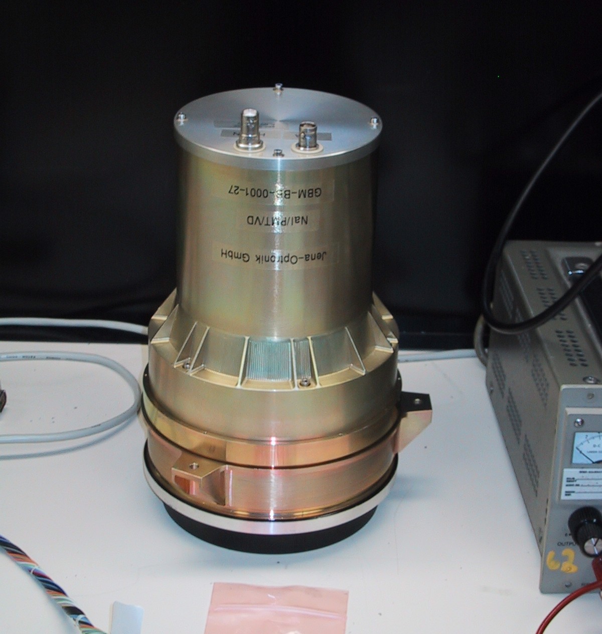
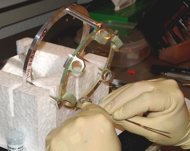
NaI Detector shipped from Jena Optronik August 2002
The 12 NaI detectors are 1.27 cm thick by 12.7 cm diameter, directly coupled to a 12.7 cm diameter photomultiplier tube (PMT). They provide spectral coverage from about 8 keV to 1 MeV. NaI is an ideal scintillation material for this energy range combining low cost, high efficiency, and adequate spectral resolution. The thickness of the detectors is optimum for the energy range where bursts typically emit the most energy and provides approximately a cosine angular response, which is important for determining locations using relative rates, similar to BATSE. Lower energy coverage relative to BATSE is obtained by using a 0.25 mm beryllium window to the detectors. The detectors are arranged in 4 banks of 3 detectors so that the larger number of detectors, each viewing a smaller field-of-view, reduces systematic errors for burst locations and allow an improved triggering algorithm.
Each of the 2 BGO detectors is 12.7 cm in diameter, 12.7 cm thick, and is viewed by 2 PMTs for improved resolution and redundancy. The Bismuth Germanate (BGO) detectors provide spectral coverage from about 150 keV to 40 MeV. BGO is a high-density material which provides good sensitivity over this difficult energy range. The energy resolution of the 12.7 cm by 12.7 cm cylindrical BGO crystal is 14% at 661 keV and 4% at 10 MeV and there is significant overlap with the lower energy range of the LAT. Each BGO detector is coupled to 2 PMTs on opposite sides, whose outputs are summed, each with its own high-voltage control. This design allows a homogeneous light collection over the detector volume and also provides redundancy should one of the PMT's fail or degrade. The BGO detectors are positioned on opposite sides of the LAT, providing nearly full sky coverage.

The GBM baseline triggering scheme is similar to BATSE. Two detectors are required to be above a threshold specified in standard deviations above background in the 50-300 keV energy range on a 1.024 second time-scale (although other time-scales and energy ranges are used). Rather than process the signals at each detector, the centrally located Data Processing Unit (DPU) collects, processes, and packages data from all the individual detectors. The main functions of the DPU are to digitize the analog pulse height signals, accumulate time-resolved pulse height spectra with variable time resolution, tag the spectra with time and detector information, package the data for telemetry, and use the data to realize a burst trigger and compute burst locations. The DPU also controls the operation of the instrument, including power supply settings, and accumulates housekeeping and instrument status data for inclusion in the telemetry. It acts as the sole electrical interface between the GBM and the Fermi spacecraft computer. Burst alerts and onboard burst locations provide the possibility of relocating the Fermi spacecraft to position the burst in the field-of-view of the LAT.
BATSE and GBM Characteristics
| BATSE | GBM | |
|---|---|---|
| TOTAL MASS | 850 kg | 115 kg |
| TRIGGER THRESHOLD | ~0.2 ph/cm2/s | 0.61 ph/cm2/s (true threshold) |
| TELEMETRY RATE | 3.55 kbps | 15 - 25 kbps |
| Large Area Detectors | Low-Energy Detectors | |
| Material | NaI | NaI |
| Number | 8 | 12 |
| Area | 2025 cm2 | 126 cm2 |
| Thickness | 1.27 cm | 1.27 cm |
| Energy range | 25 keV to 1.8 MeV | 8 keV to 1 MeV |
| Spectroscopy Detectors | High-Energy Detectors | |
| Material | NaI | BGO |
| Number | 8 | 2 |
| Area | 126 cm2 | 126 cm2 |
| Thickness | 7.62 cm | 12.7 cm |
| Energy range | 30 keV to 10 MeV | 150 keV to 40 MeV |
GBM Requirements and Capabilities
| PARAMETER | REQUIREMENT | GOAL | CURRENT CAPABILITY |
|---|---|---|---|
| Energy Range | 10 keV -- 25 MeV | 5 keV -- 30 MeV | ~8 keV -- 30 MeV |
| Energy Resolution | 20% FWHM at 511 keV | (no stated goal) | 12% FWHM at 511 keV |
| Time resolution | 10 μsec | 2 μsec | 2 μsec |
| On-board GRB Locations | 15° accuracy (1 σ radius) within 2 sec | 10° within 1 sec | < 15° in 1.8 sec (< 8° for S/C < 60° zenith) |
| Rapid ground GRB Locations | 5° accuracy (1 σ radius) within 5 sec | 1° within 1 sec | TBD by analysis scattering influenced) |
| Final GRB Locations | 3° accuracy (1 σ radius) within 5 sec | (no stated goal) | TBD by analysis (stattering influenced) |
| GRB sensitivity (on ground) | 0.5 photons cm2s-1 (peak flux, 50--300 keV) | 0.3 photons cm2s-1 (peak flux, 50--300 keV) | ~0.4 photons cm2s-1 (peak flux, 50--300 keV) |
| GRB on-board trigger sensitivity (50% efficiency) | 1.0 photons cm2s-1 (peak flux, 50--300 keV) | 0.75 photons cm2s-1 (peak flux, 50--300 keV) |
0.71 photons cm2s-1 (peak flux, 50--300 keV |
| Field of view | 8 steradians | 10 steradians | 9.5 steradians |
| Deadtime | < 10 μsec/count | < 3 μsec/count | < 2 μsec/count |
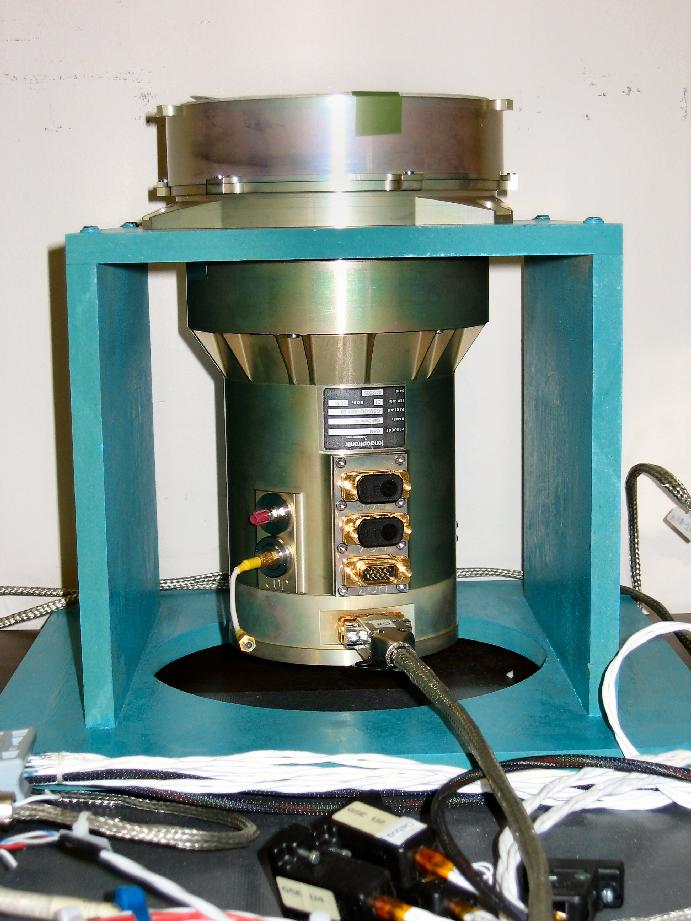
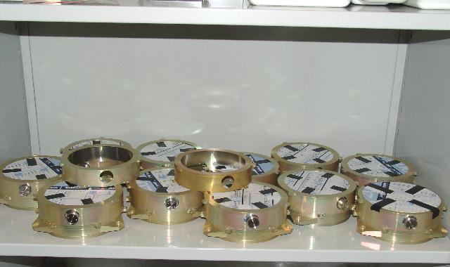
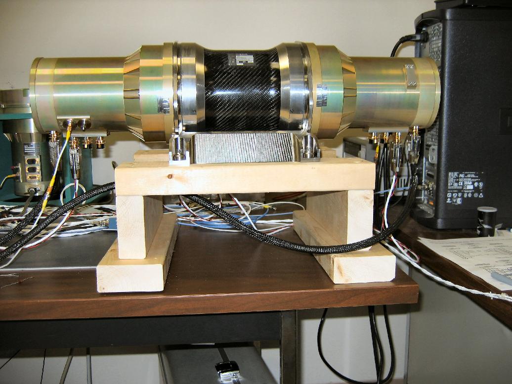
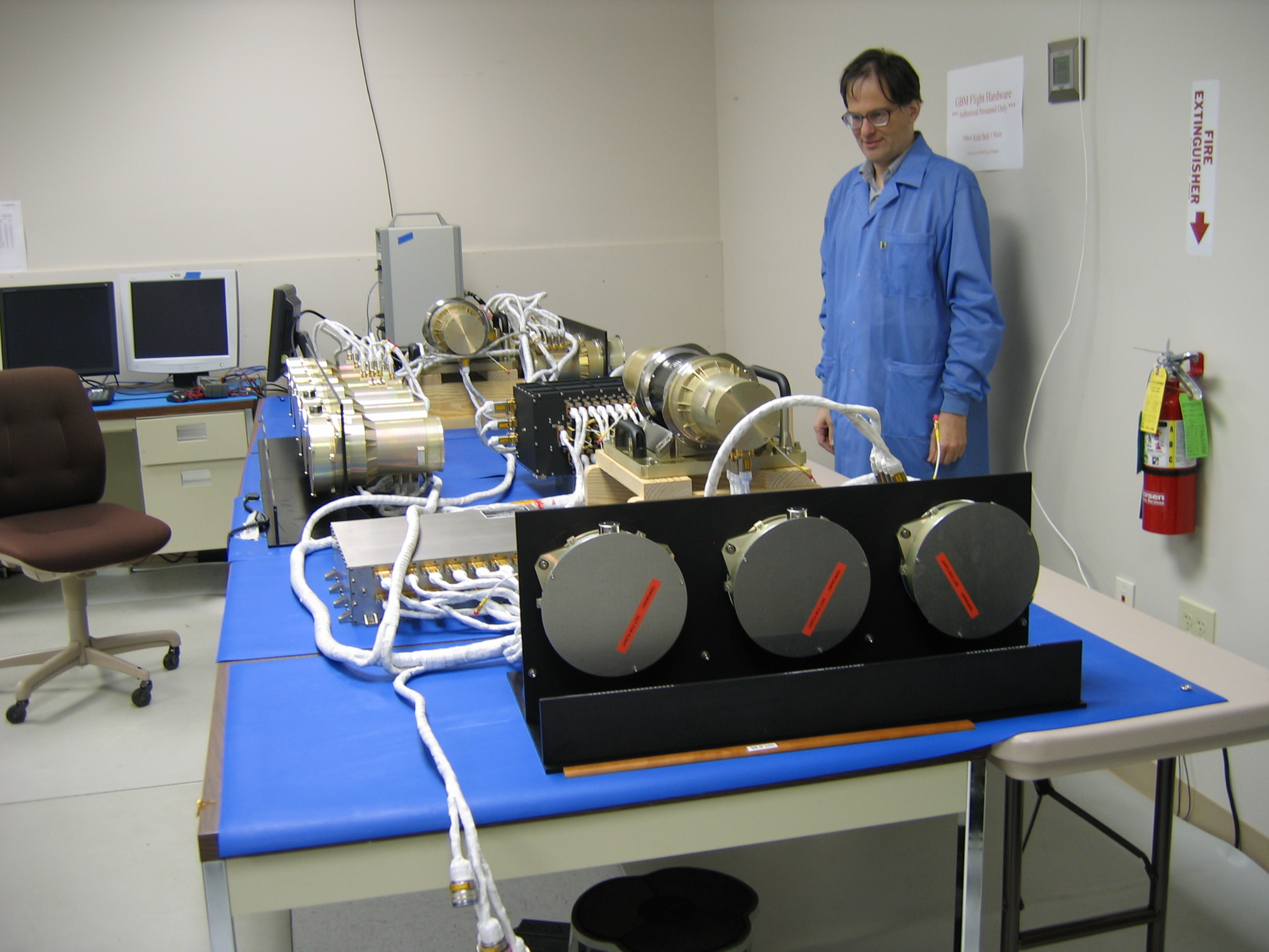
Detector Acceptance

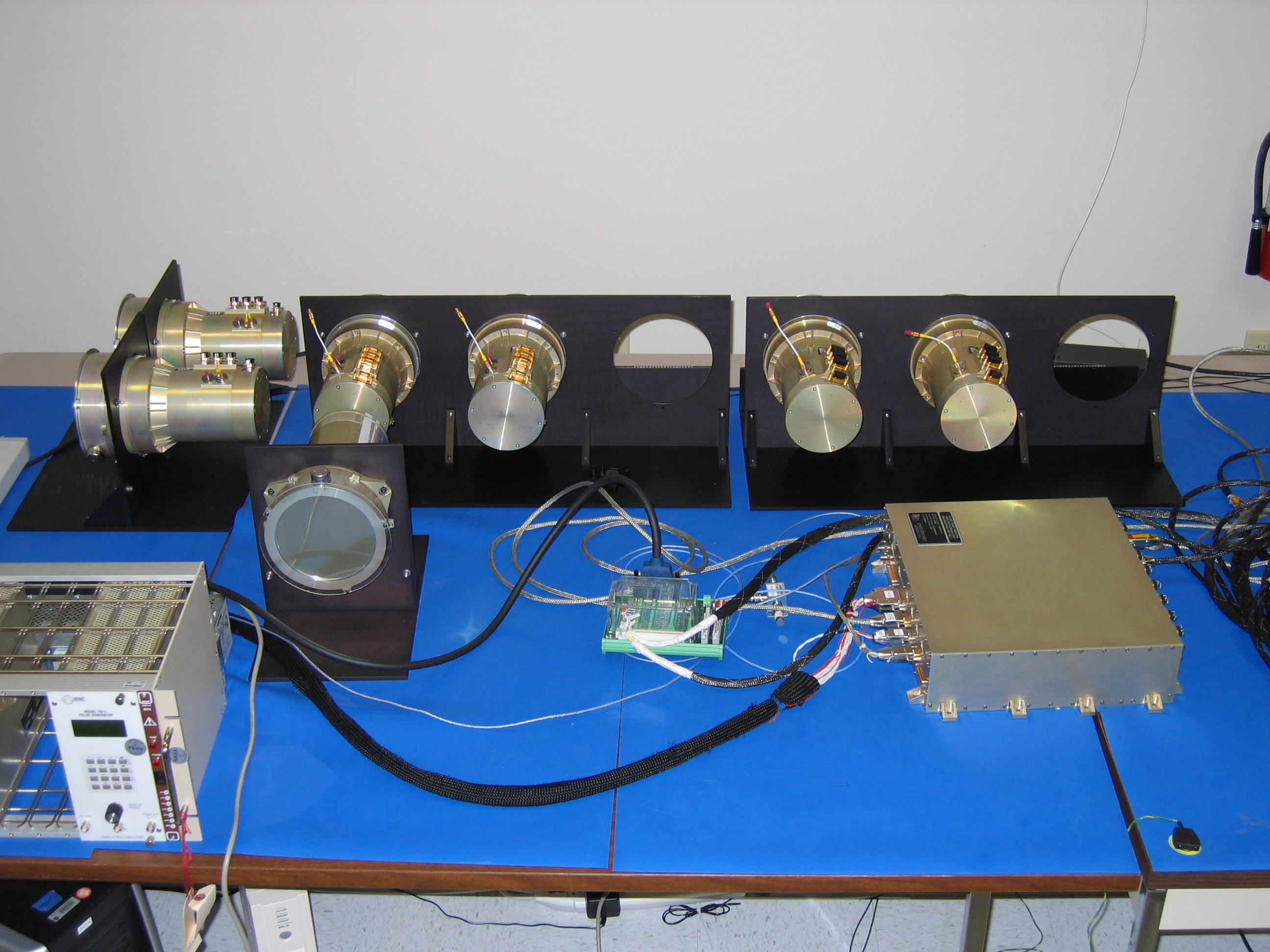
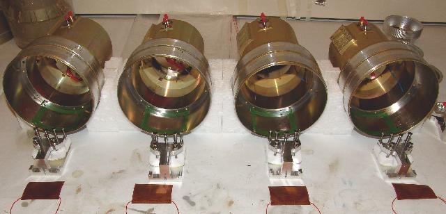
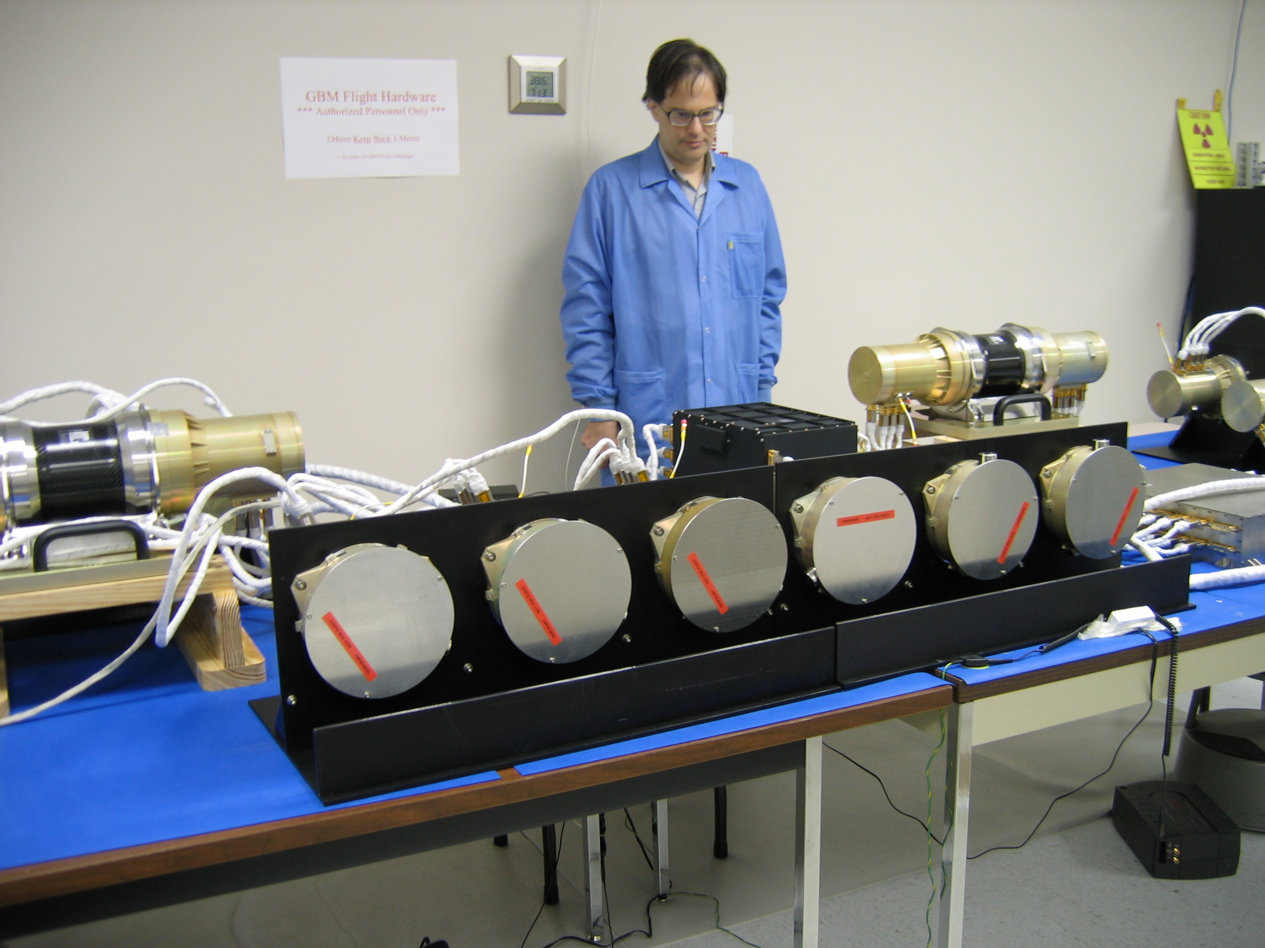
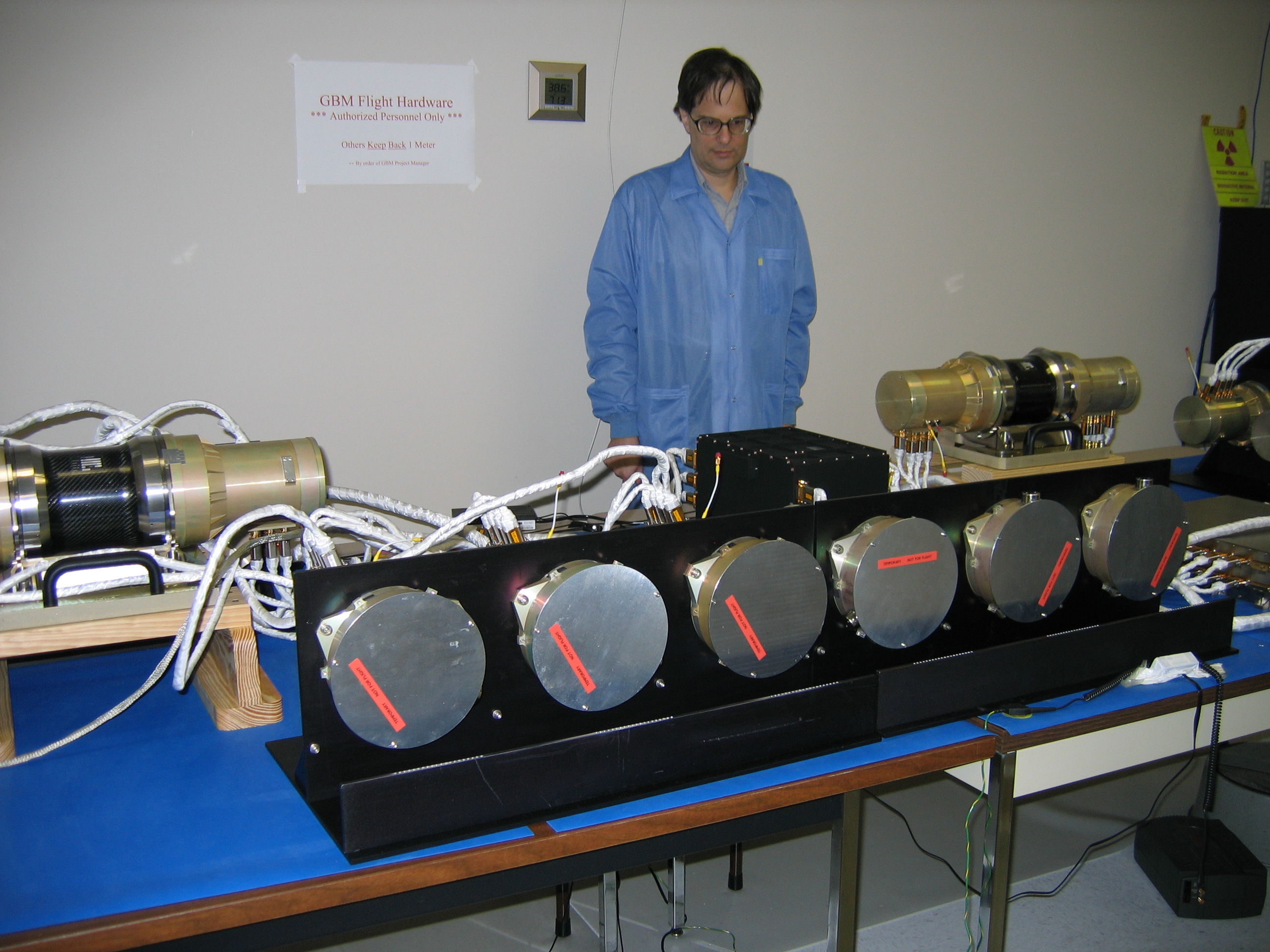
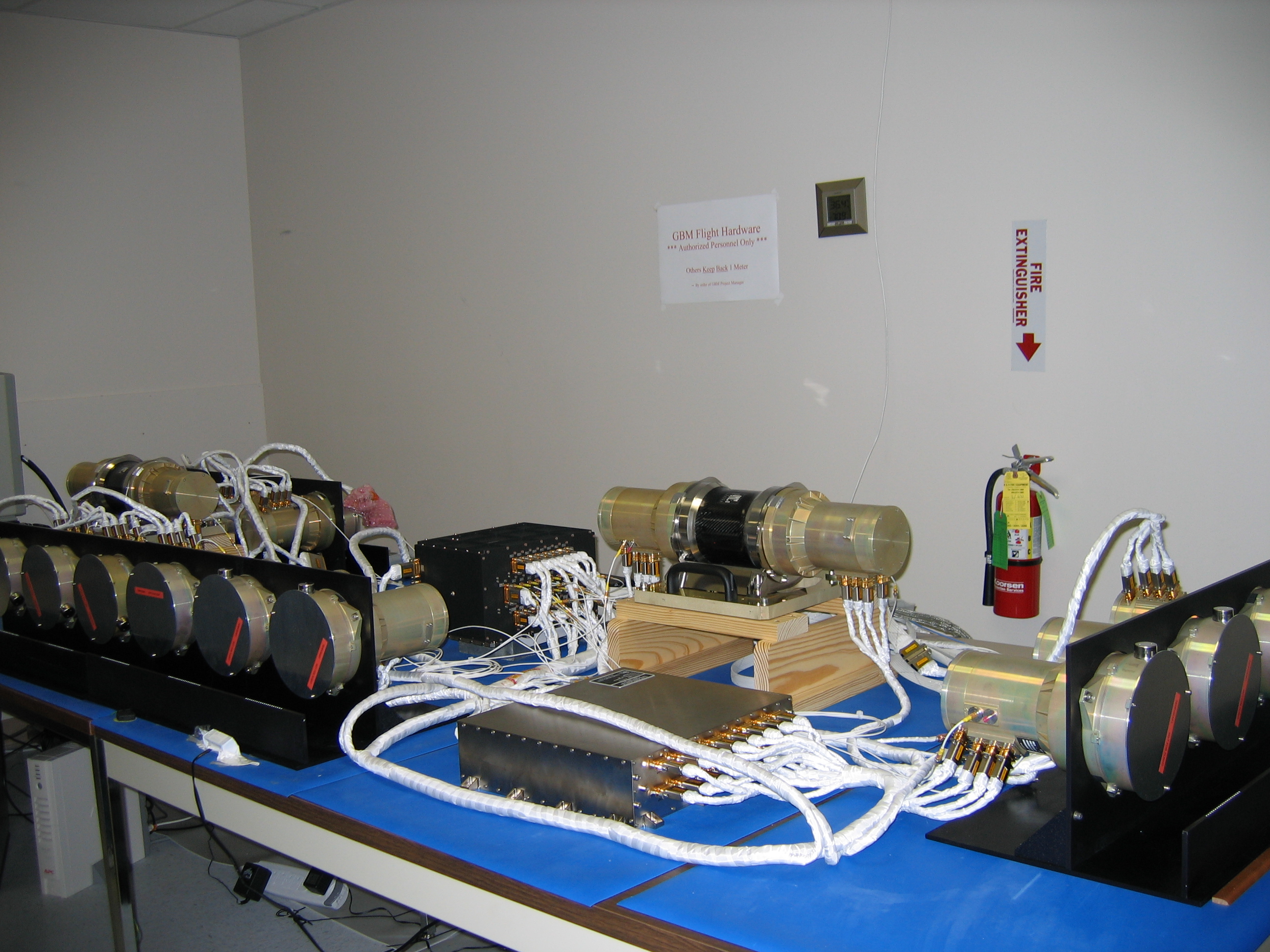
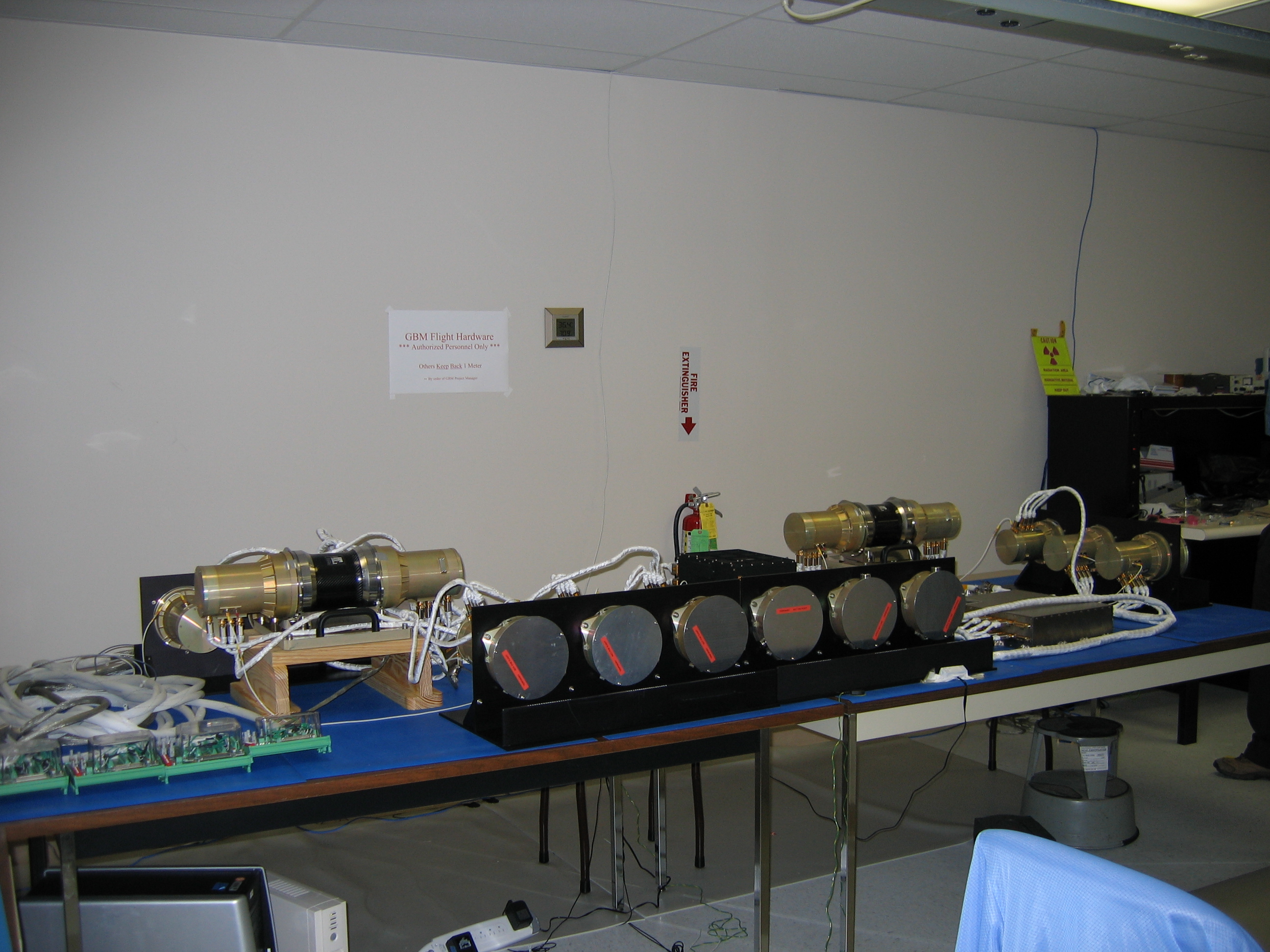
First Integration
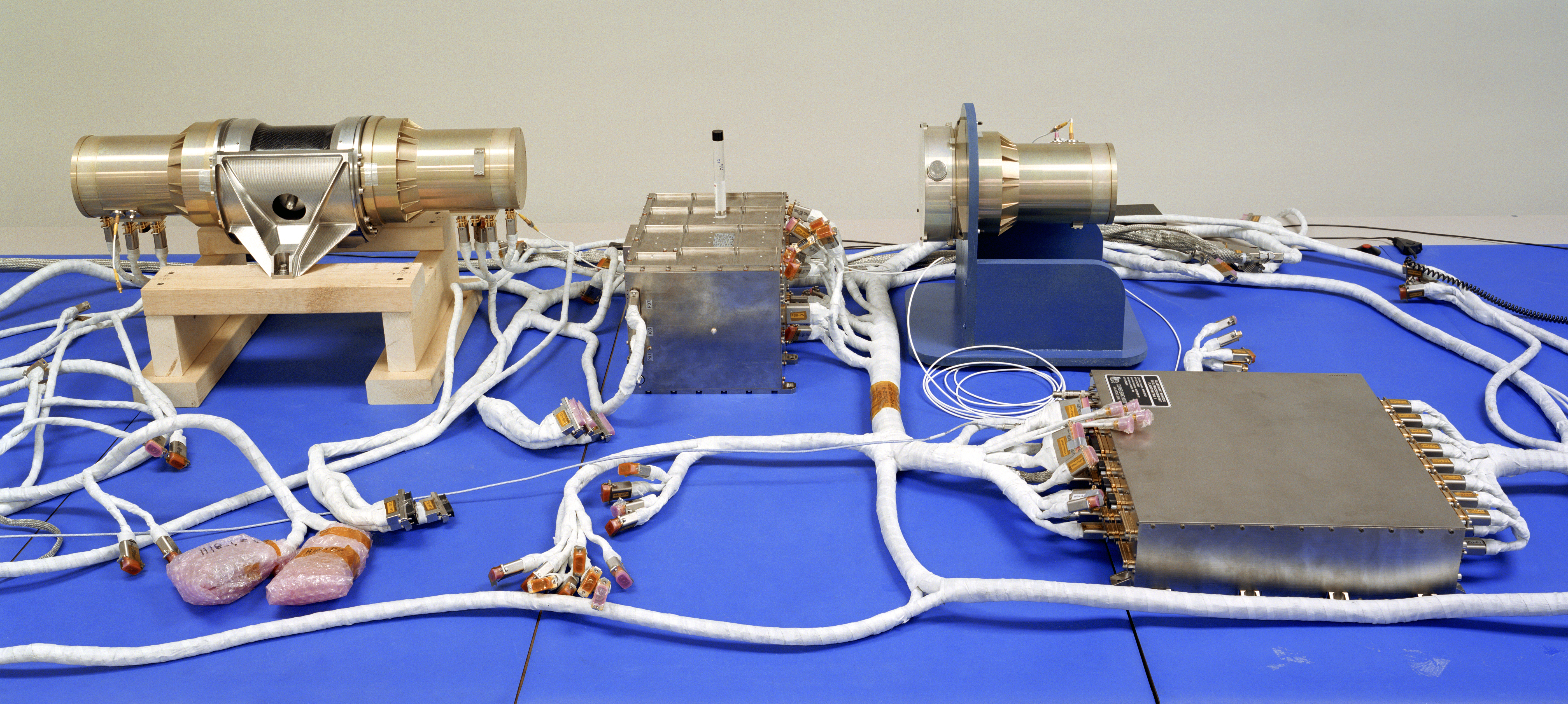
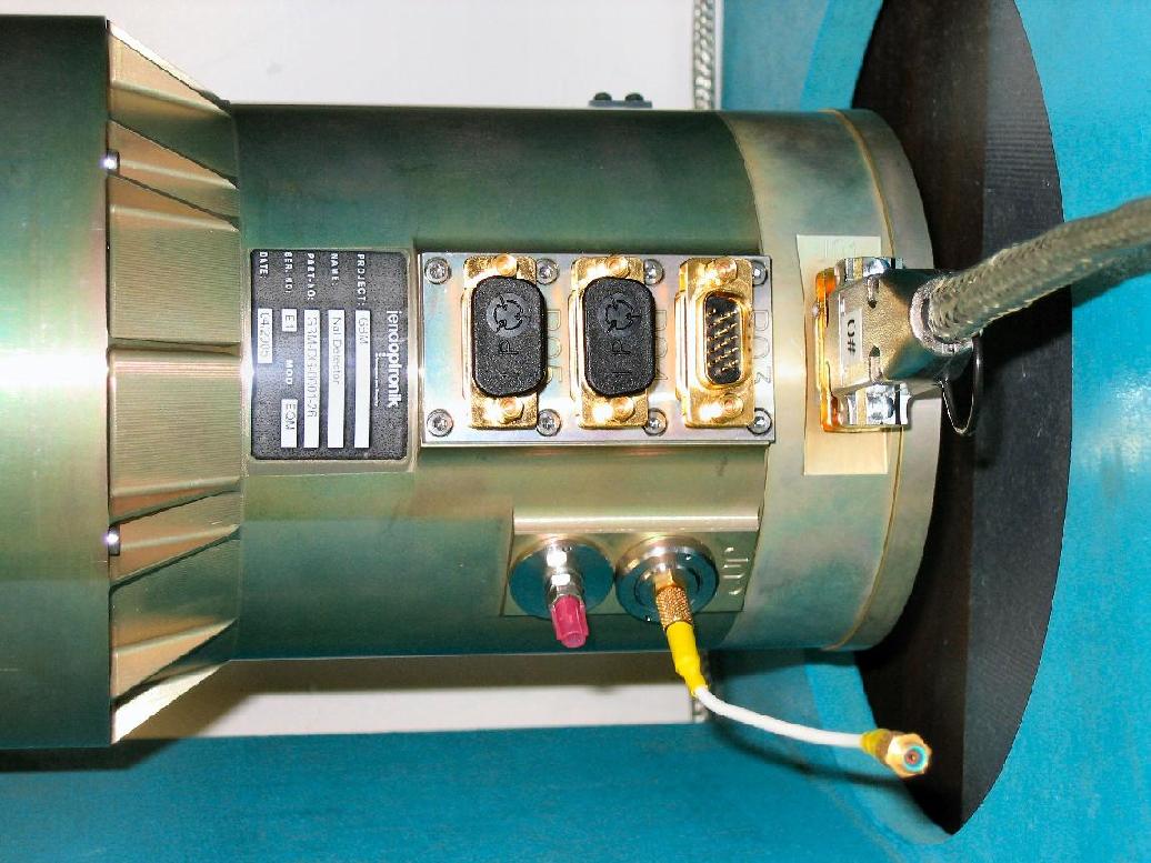
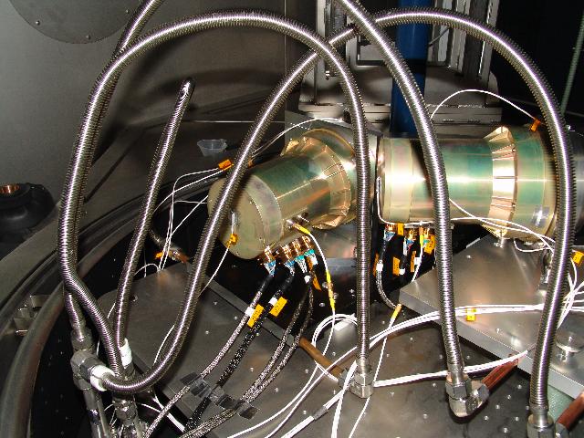
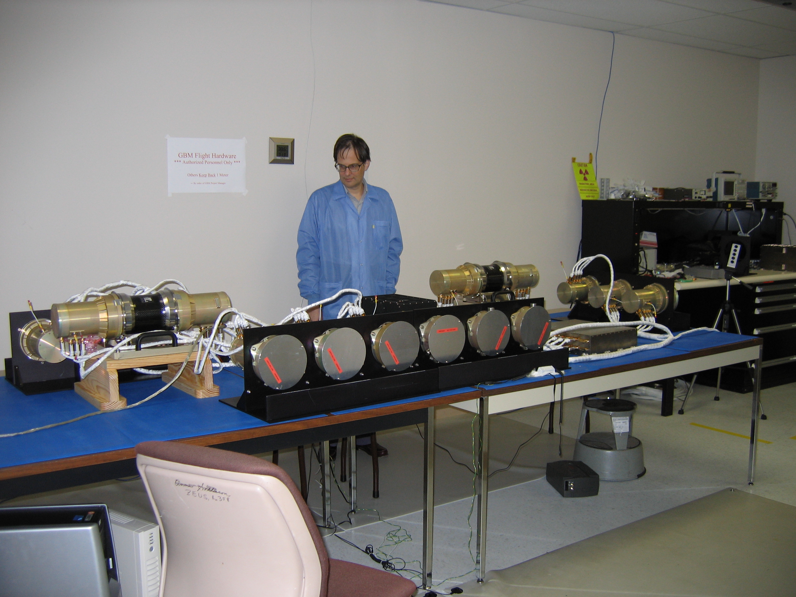
System Integration

Author: Michael S. Briggs
Responsible Manager: Steve Elrod
Site Curator: Cori Fletcher